Call us now: 888 540-2010, 416 833-3501 10am – 6pm ET
|
|
Atola Insight
All-in-one hard drive data recovery system
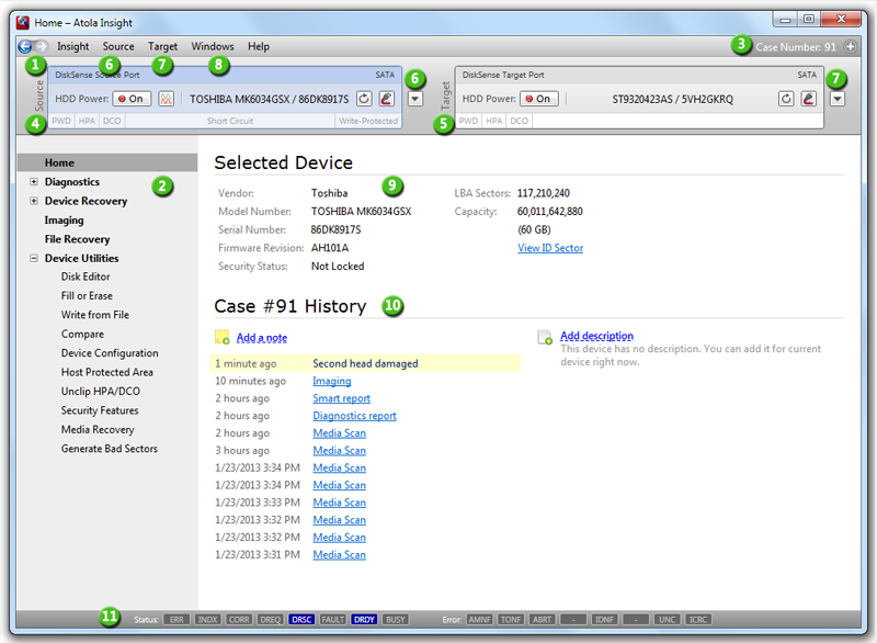
Atola Insight: Main WindowThis page provides information on basic Atola Insight controls.
1. Back and Forward buttonsThese buttons allow you to go to the previous screen of the program. This may be useful if you'd like to see your previous input or quickly restart a process. 2. Main menuYou use this menu to navigate through different parts of the software.3. CaseThis panel shows the current case number or allows assigning a case number. The panel also provides a menu that allows browsing cases, clear device history, etc.
4. Source Port controls and indicators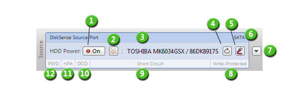
5. Target Port controls and indicatorsTarget port has almost all features of Source port with the exception of:
Target port allows to plug one of the following:
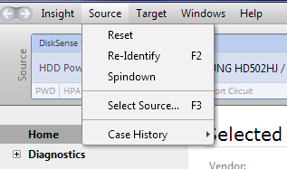
6. SourceSource port menu allows performing the following operations:
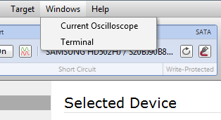
7. TargetTarget port menu allows performing the same operations for any target selection as for the source port (see 6. Source). 8. WindowsThis menu is used to open the Current Oscilloscope and Terminal windows. It also allows enabling DiskSense controls and IDE/SATA registers (in case you have previously closed them).
9. Selected device informationThis panel shows detailed information about the currently attached device. If you'd like to see even more details, click View ID Sector link and you will see the full ID sector that was returned by the hard drive.10. Case historyHere you can see all actions that were done to the currently attached hard drive. If you'd like to get full details on an action, just click it and Atola Insight will show you the detailed log of that action. 11. Status and Error registersThis panel displays raw contents of Status and Error ATA registers in real time. Back to Atola Insight User's Manual |